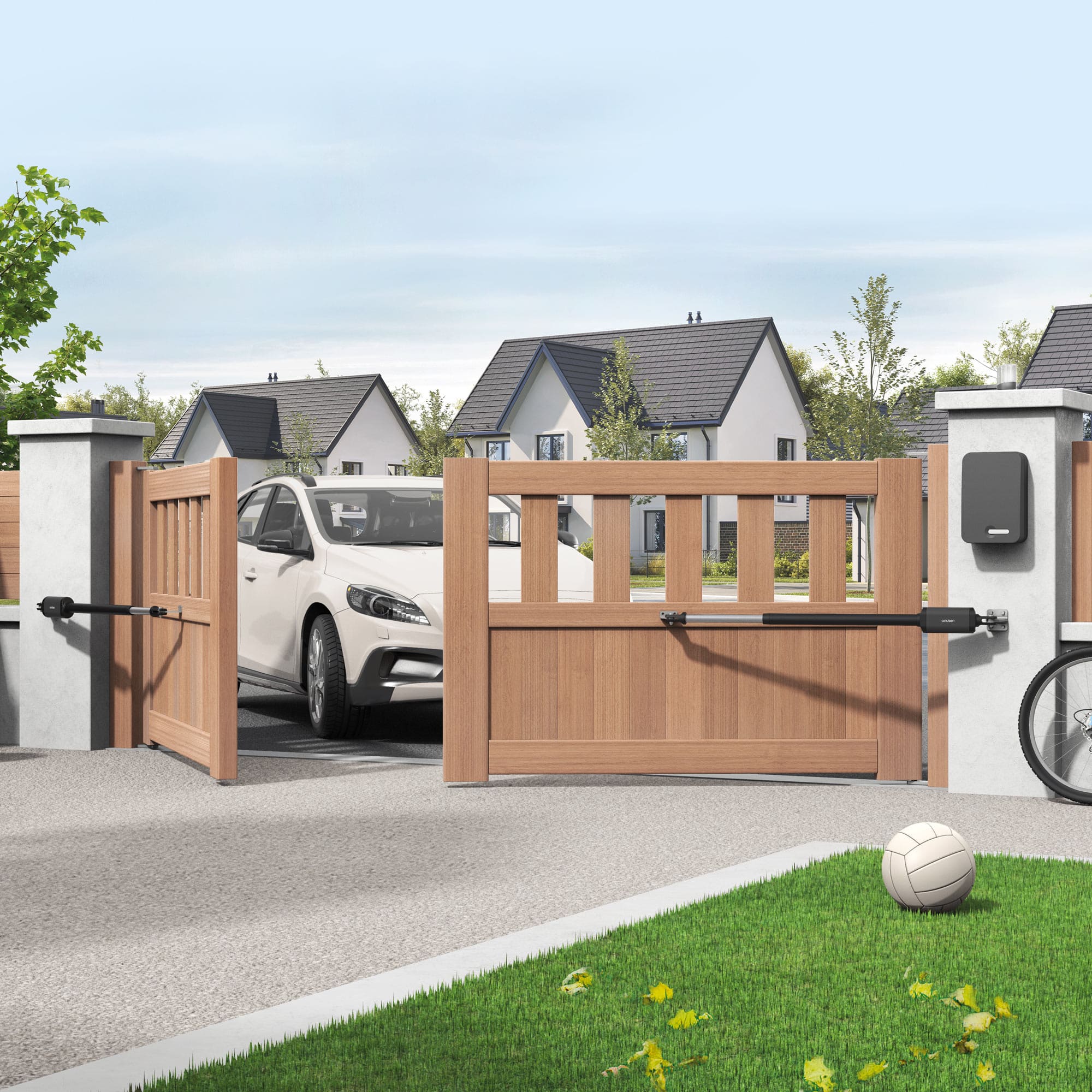
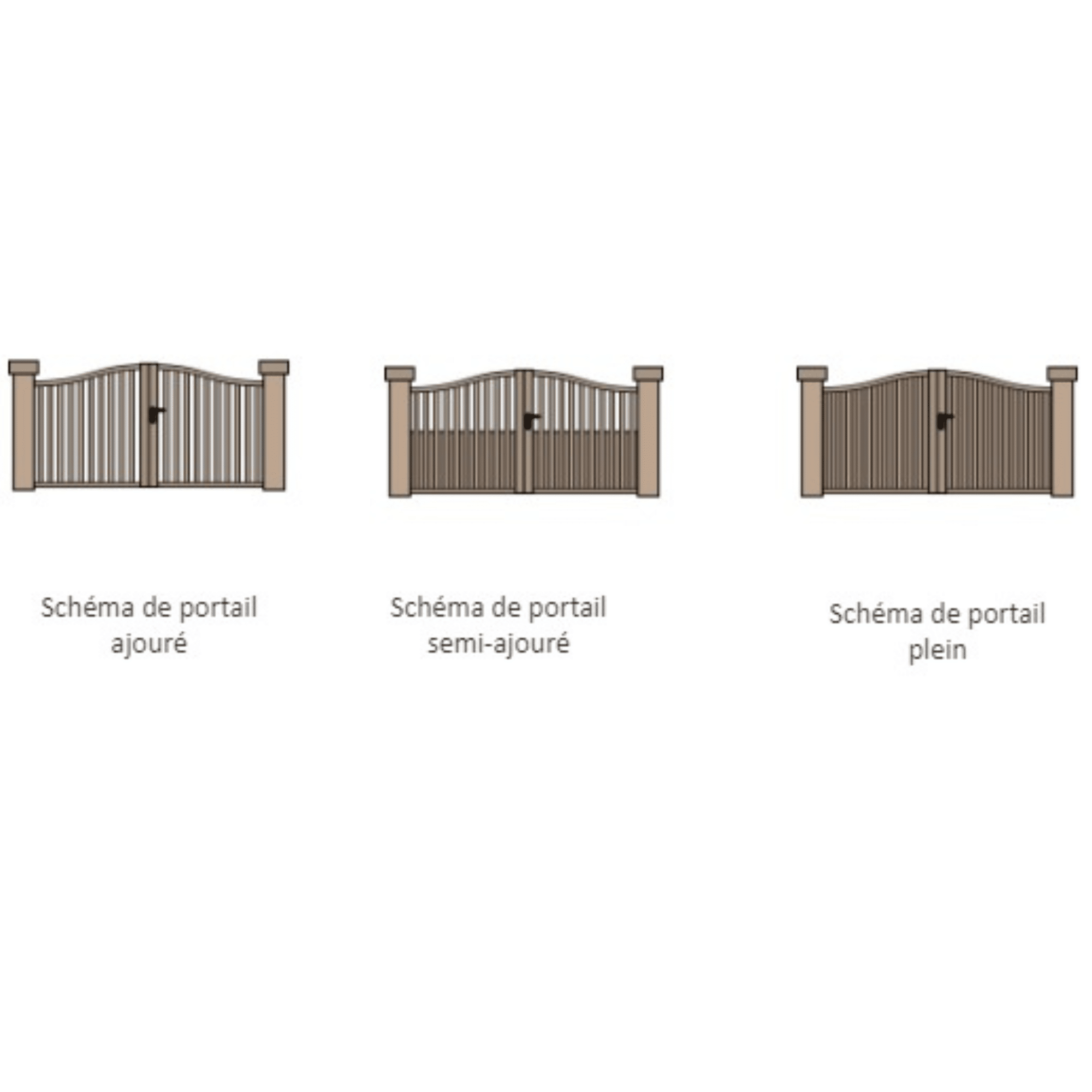
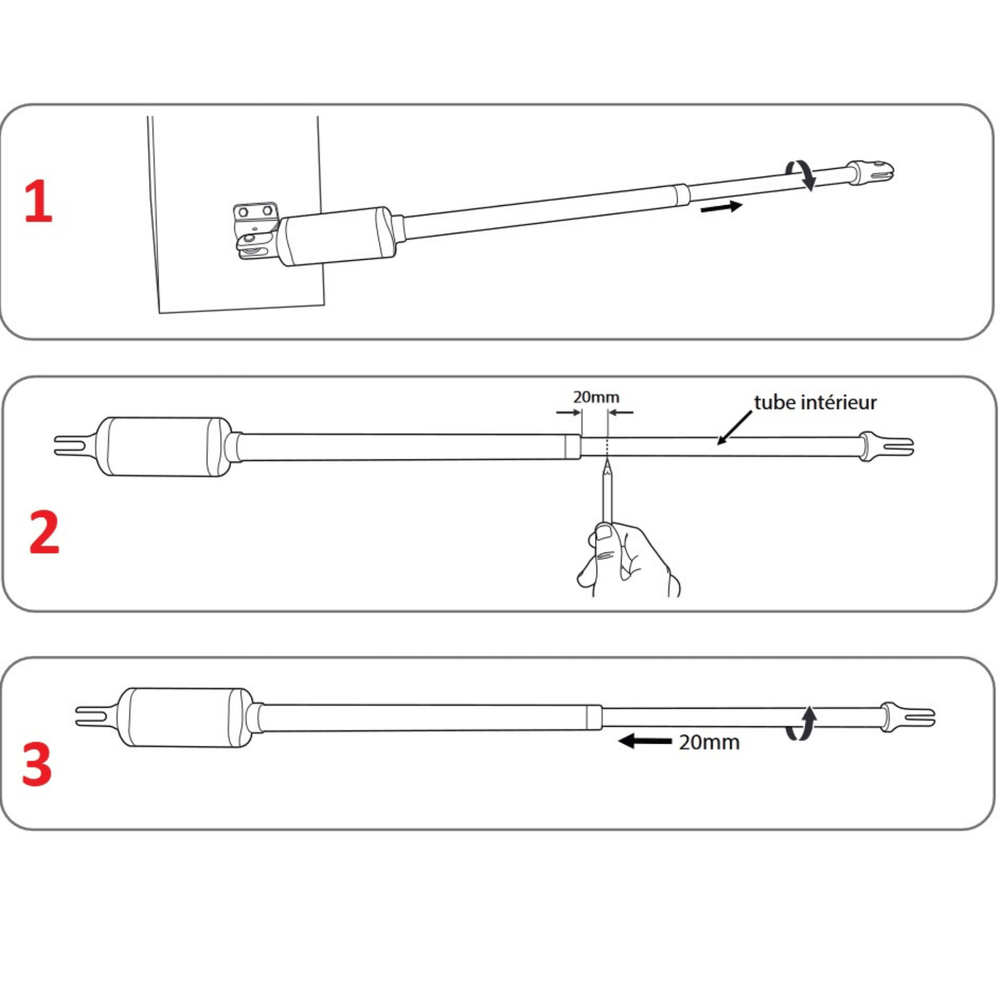
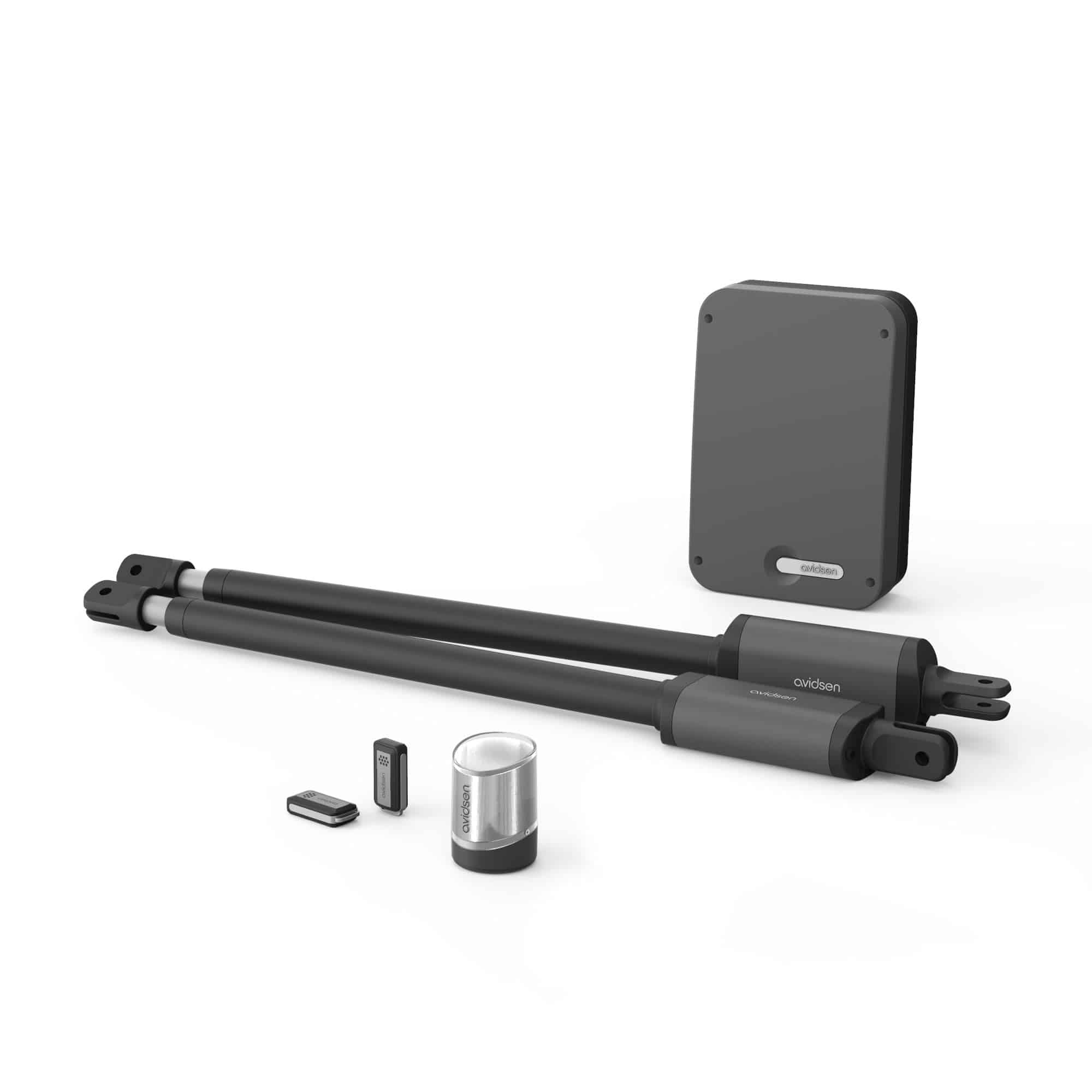
The STYRKA 310 motorization can operate a gate with one or two leaves, up to a maximum length of 2.50 m, in the case of a light, openwork gate. In the case of semi-open, heavy gates, the size of the leaf should be smaller.
The leaves can be asymmetrical (of different sizes) as long as the largest leaf does not exceed the size limit supported by the operator.
It is not recommended to install this motorization on a solid gate.
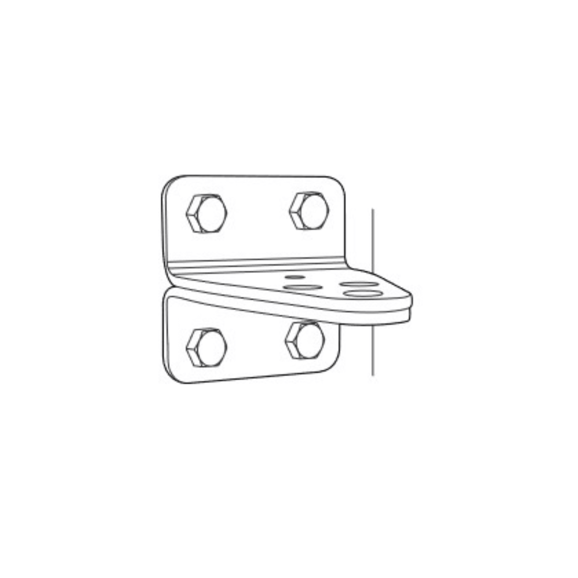
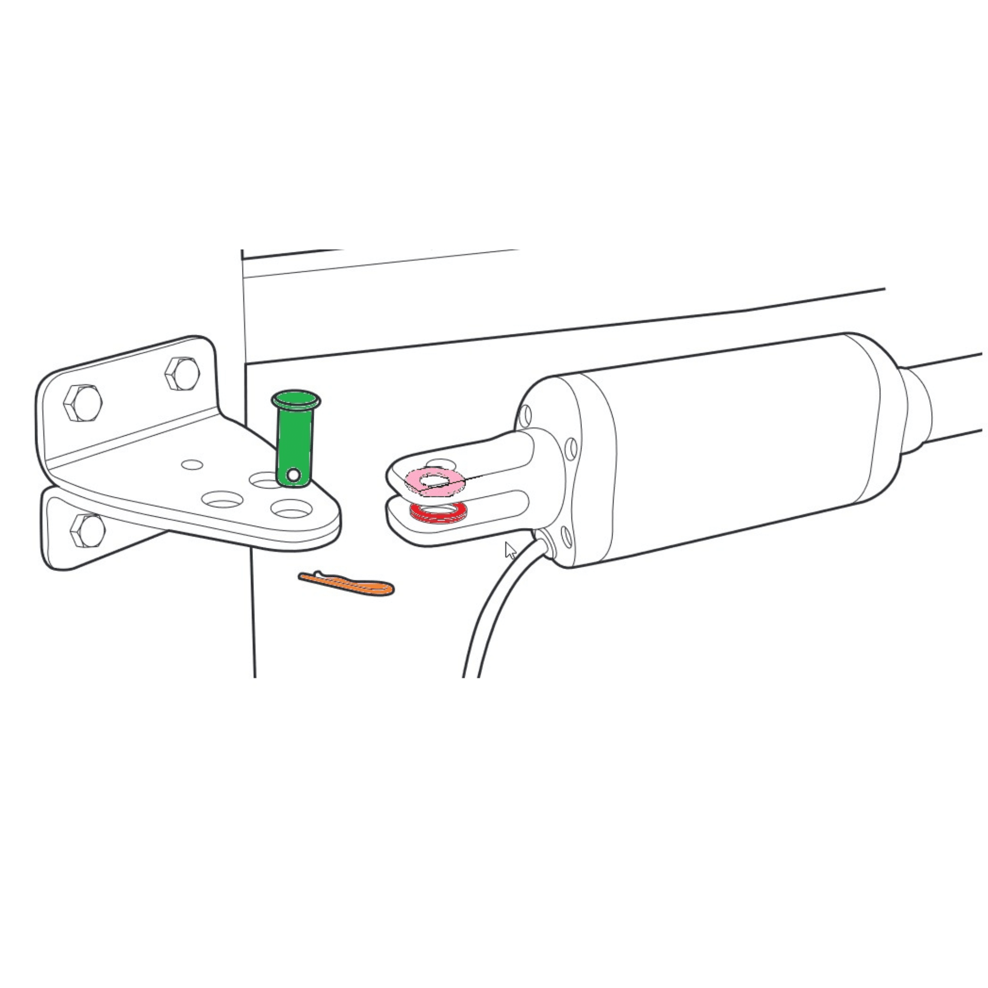
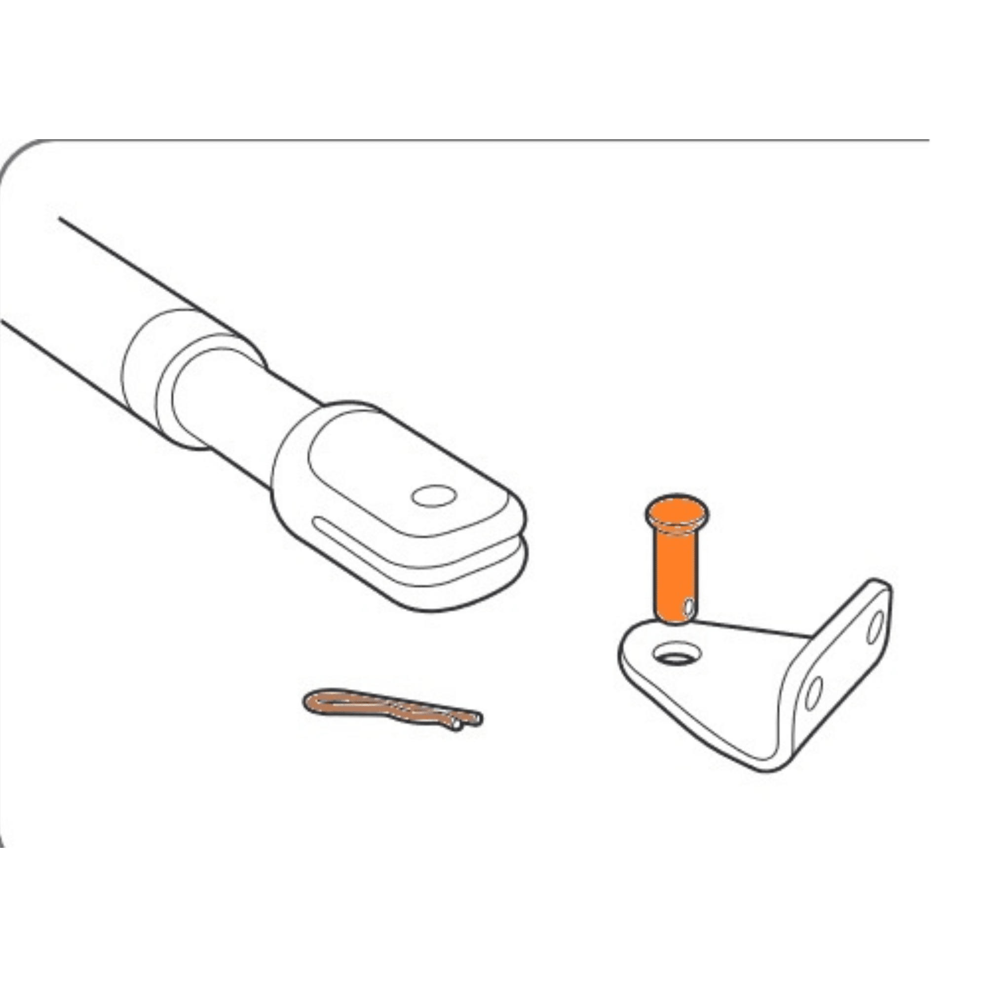
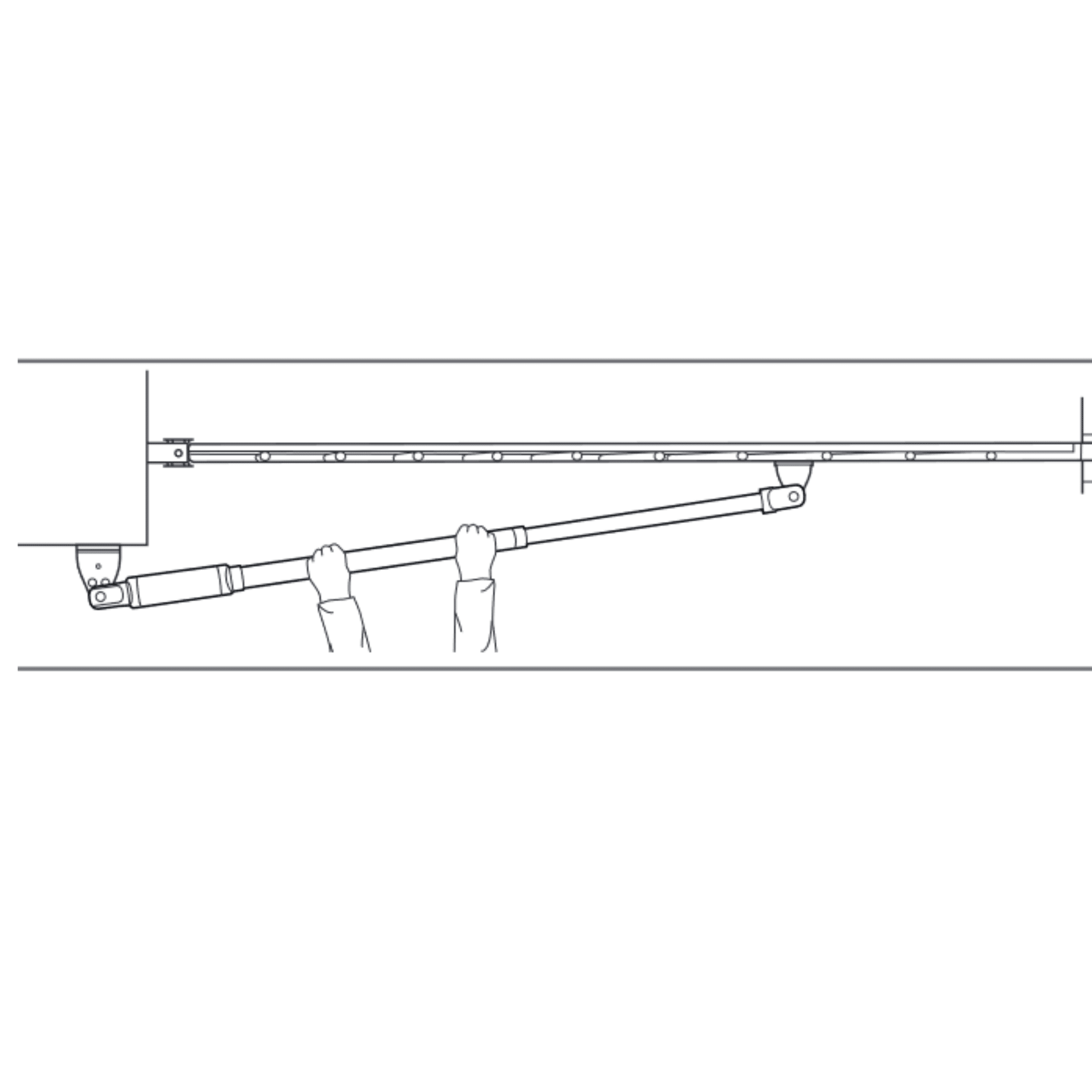
The gate must be fitted with a reinforcement point, to which the operator can be attached.
The gate must be stable and balanced (it must not open or close by itself without external action).
The gate must open and close smoothly.
The gate must open towards the interior of the property, on both sides.
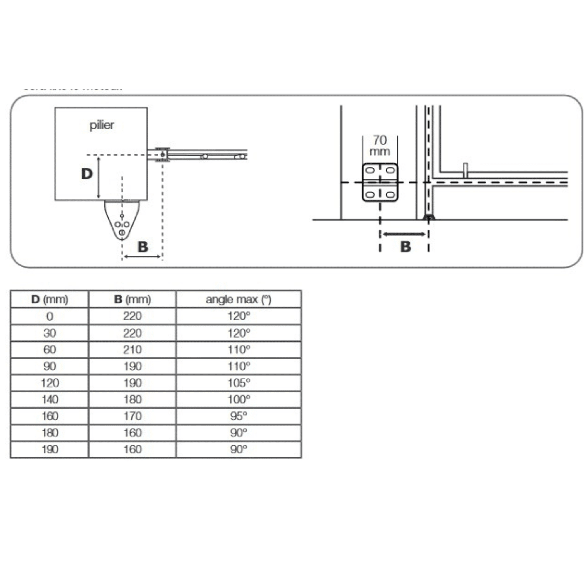
Its maximum opening angle must not be less than 60°.
The pillar must be large enough to correctly accommodate the actuator bracket.
The pillar must not be rounded on the side receiving the actuator bracket.
The distance B materialized will depend on distance D (see Table Step 1 Measurements on the pillar).
The image shows the minimum and maximum distances at which the bracket can be fixed (with D=0 cm and D=19 cm).
The pillar must be clean and dry, and free of any fixings from an old motorization model.
It is imperative to maintain a safe lateral clearance between the open gate and any fixed part of the environment.
The floor must be straight and even. The gate must not rub against the floor.
The drive unit is not compatible with sloping entrances, either upwards or downwards.
The installation of FIXED and PERMANENT floor stops is MANDATORY for opening and closing.
The installation depth of the gate in relation to the inner face of the pillar is important. We call it distance D.
This cannot be less than 0 cm (negative distance) and cannot exceed 19 cm.
This distance determines the distance B at which the bracket is installed on the pillar (see pillar requirements).
If you have the option of adjusting the installation depth of the gate, take care to choose a location that allows you to have a distance B compatible with the width of your pillar.
If distance D is negative or greater than 19 cm, you will need to modify your pillar. In the closed position, the gate must be parallel to the rear face of the pillar on which the pillar bracket will be installed.
It is not possible to install the pillar bracket on a perimeter wall perpendicular to the gate.
It is not possible to install the pillar bracket on the same side as the gate hinges.
It is not possible to install the piston on an unreinforced part of the gate.
If the size of your pillars does not allow you to respect distance B, it will not be possible to install the motorization.
If the motors are not installed in accordance with the table below, your motorization may:
– fail to drive the leaves correctly (low opening angle, obstacle detection by the board, erratic operation, etc.), – fail to keep the leaves closed correctly, – destroy one or more of the motor’s components.),
– failure to keep the leaves properly closed,
– destruction of one or more of the motor’s components
– failure to comply with the values defined in standard NF-EN 12453, resulting in serious damage to property or personal injury. Any non-compliant installation resulting in malfunction, destruction or premature wear of the device will not be covered by the warranty.
Avidsen will not provide any technical assistance until the motorization has been installed in compliance.
Mark the location of the holes in the pillar, ensuring that the pillar bracket is fitted horizontally at the end. Use 10 mm lag bolts or any other fastening system suited to the abutment material.
Please note that the stresses on the mounting bracket will be considerable when the motorization is in operation. We recommend using threaded rods at least 15 cm long. If the pillar is made of metal, we recommend welding or threading through the threaded rods to secure them with self-locking nuts.
Consult a professional in case of doubt.
Position the piston’s rear fork on the bracket, positioning the washers above (pink) and below (red) the bracket. Insert the nipple (green) and lock with the pin (brown). Please note that the nipples supplied are not the same length. Make sure you use the longest nipple at this stage.
Close the gate and place the bracket on the gate crossbar, checking that the
motor is horizontal, then mark the location of the two holes to be drilled in the gate.
When the holes are drilled, disassemble the gate bracket from the motor by removing the pin.
Fix the bracket to the gate using through-bolts.
We strongly advise against the use of self-drilling screws, rivets or inserts.
Reassemble the motor and gate bracket.