The electronic board does not respond when a remote control button is pressed or a code is entered on the wireless keypad.
First of all, check that the remote control is working properly (indicator lights up when a button is pressed, battery replaced, etc.).
We recommend you carry out the tests using several remote controls, in order to avoid a technical problem on a single remote control.
|
|
|
|
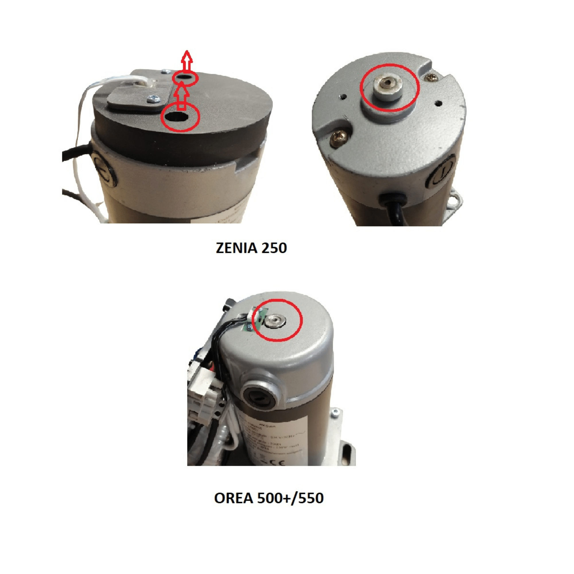
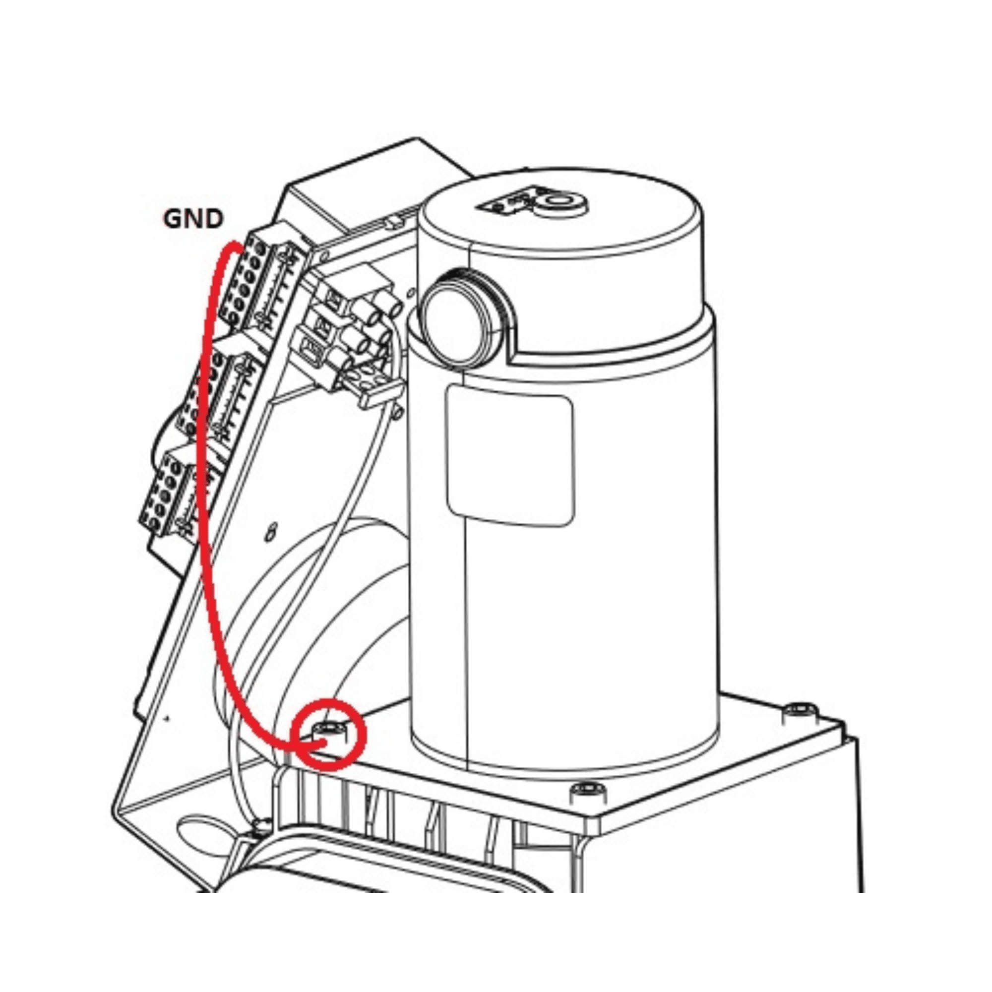
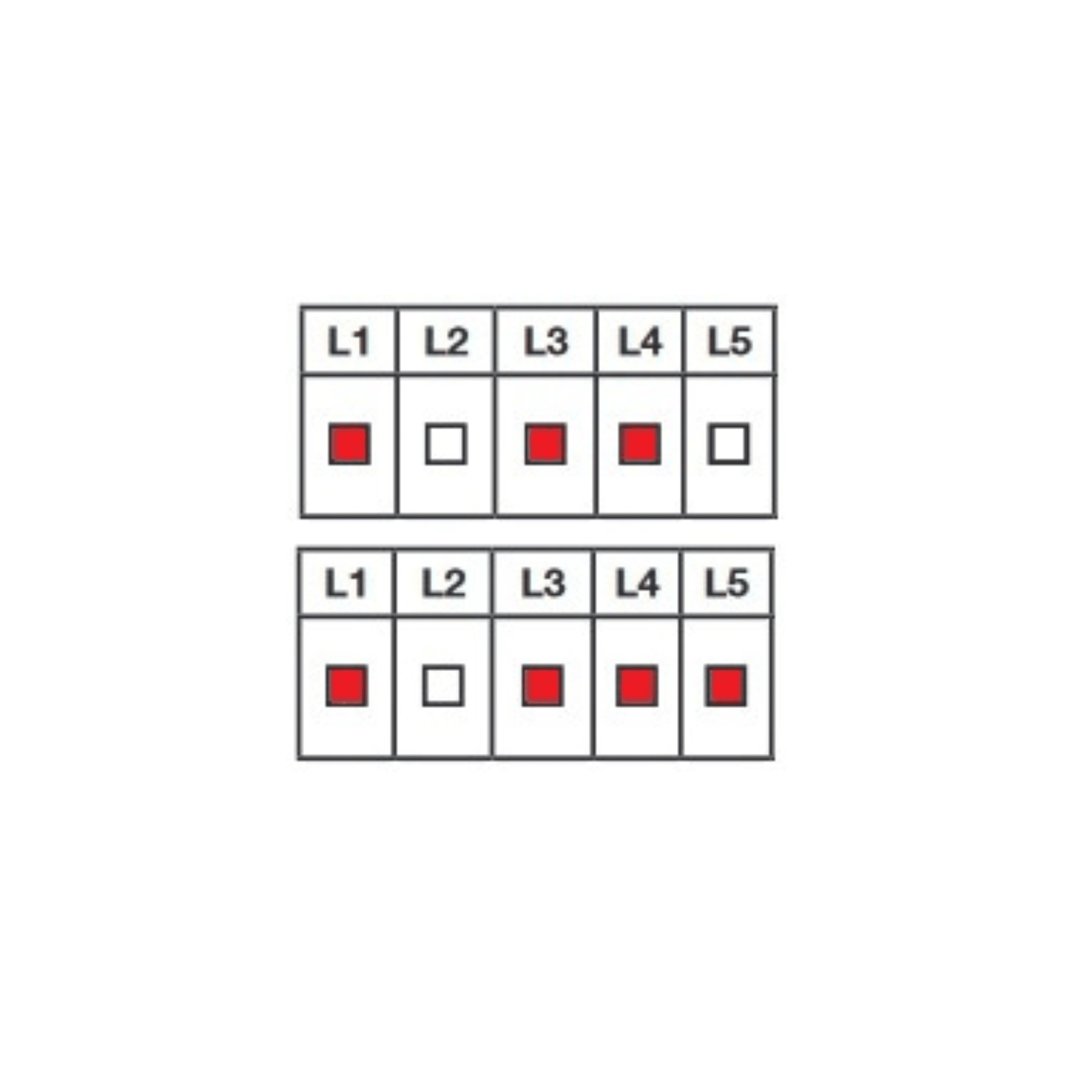
If radio range is lost :
|
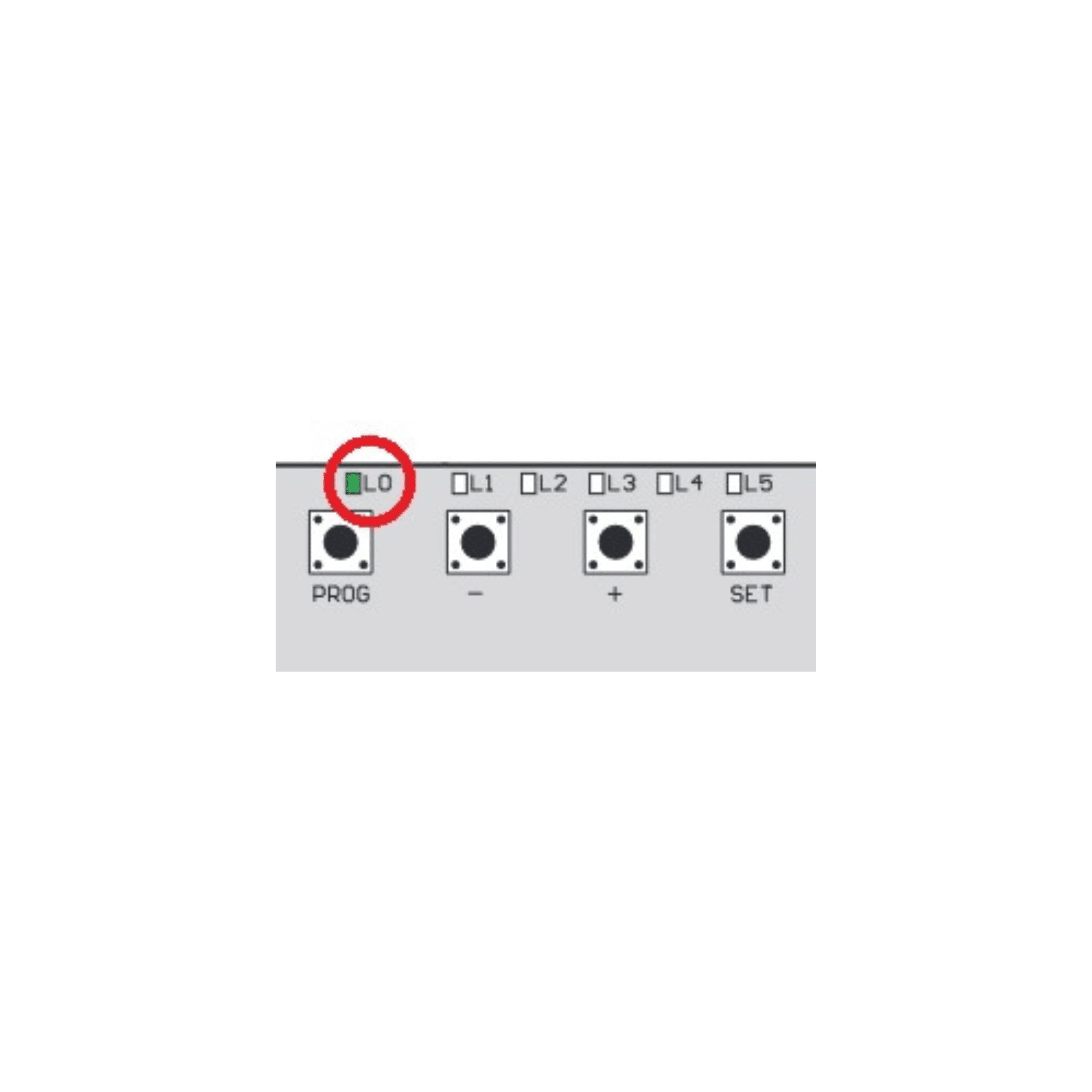
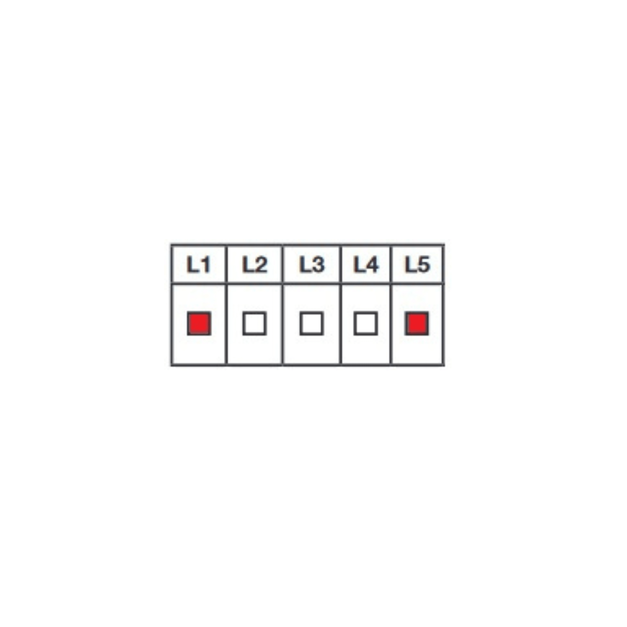
If the card reacts when it is off standby (LED L0 on) but does not react when it is on standby (LED L0 off) :
|
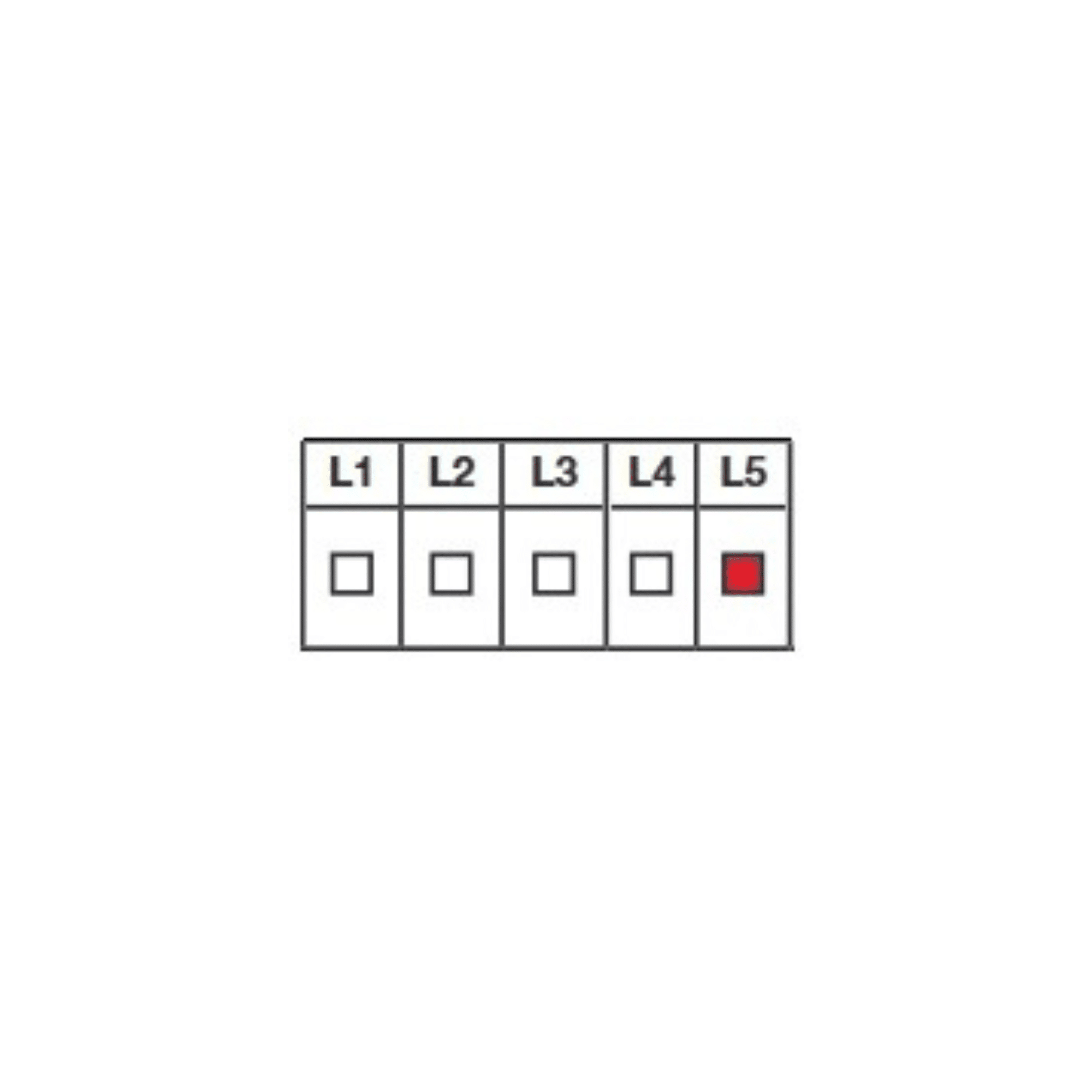
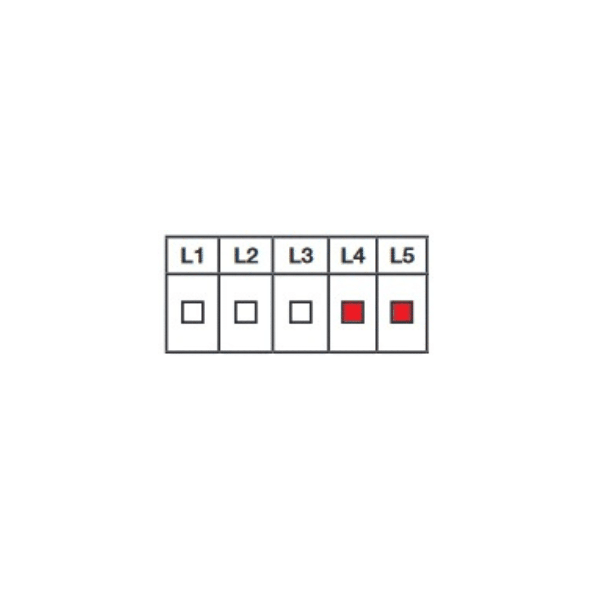
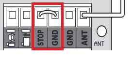
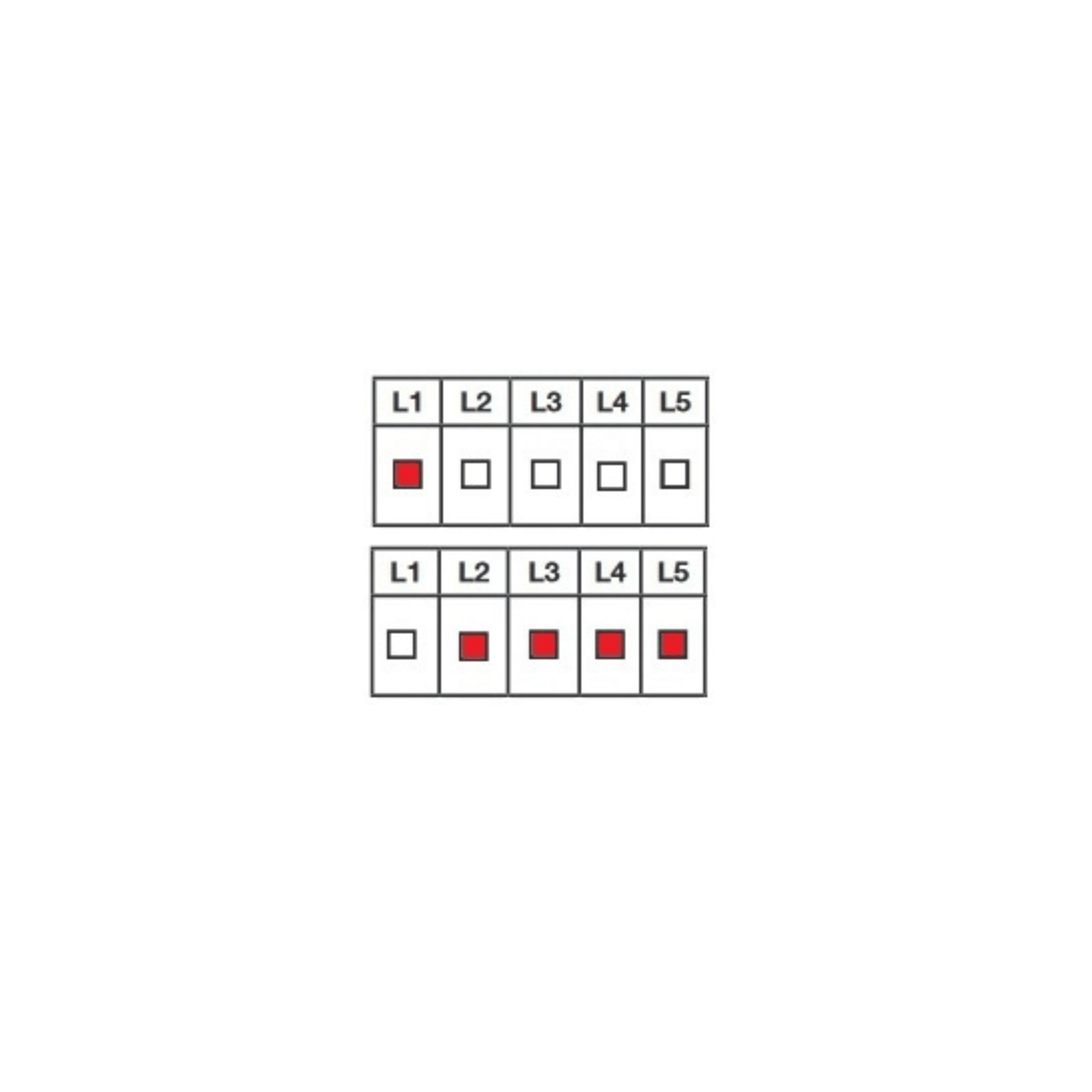
This error code appears when the card’s emergency stop circuit has been opened. This error code often occurs when the unit is switched on for the first time.
|
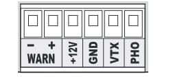
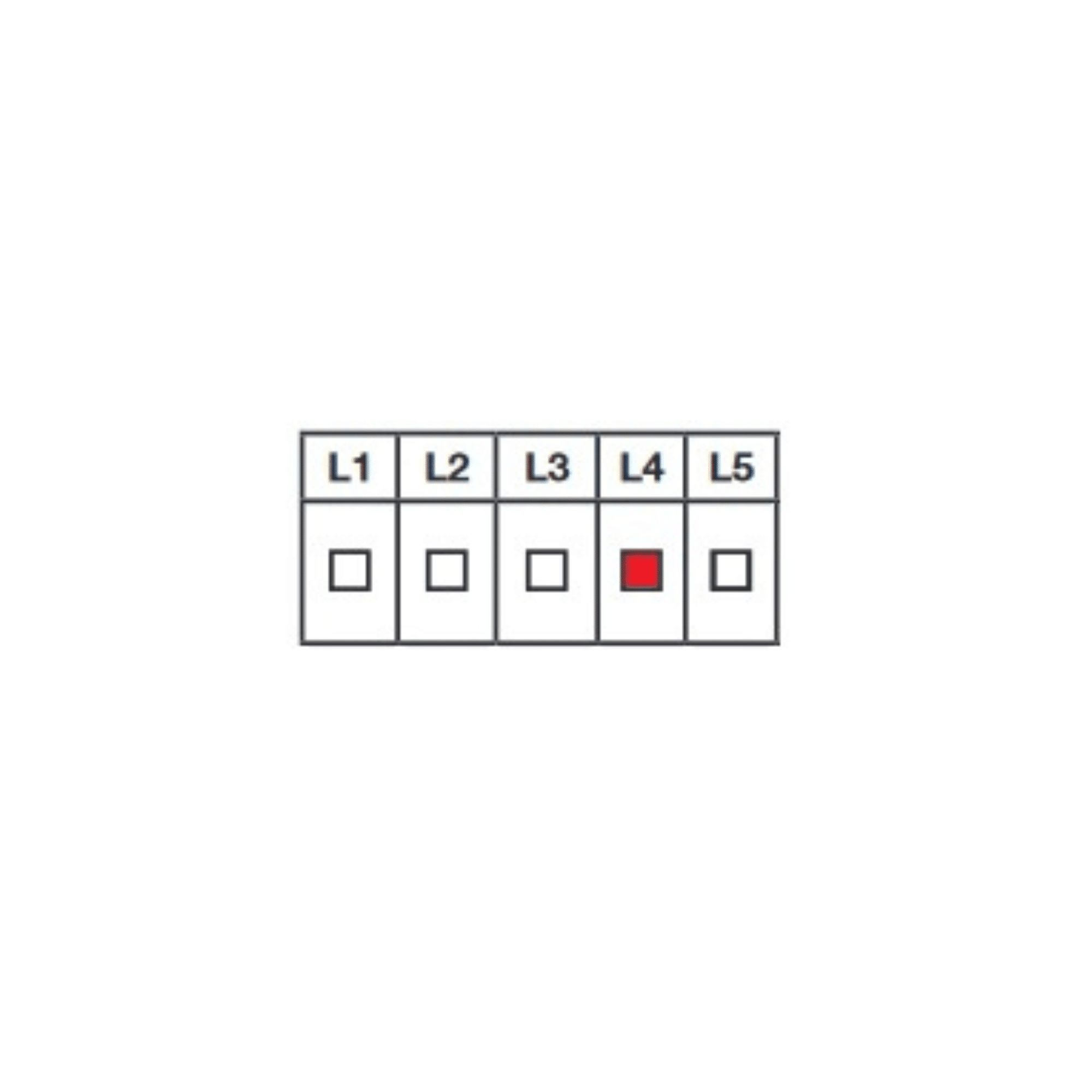
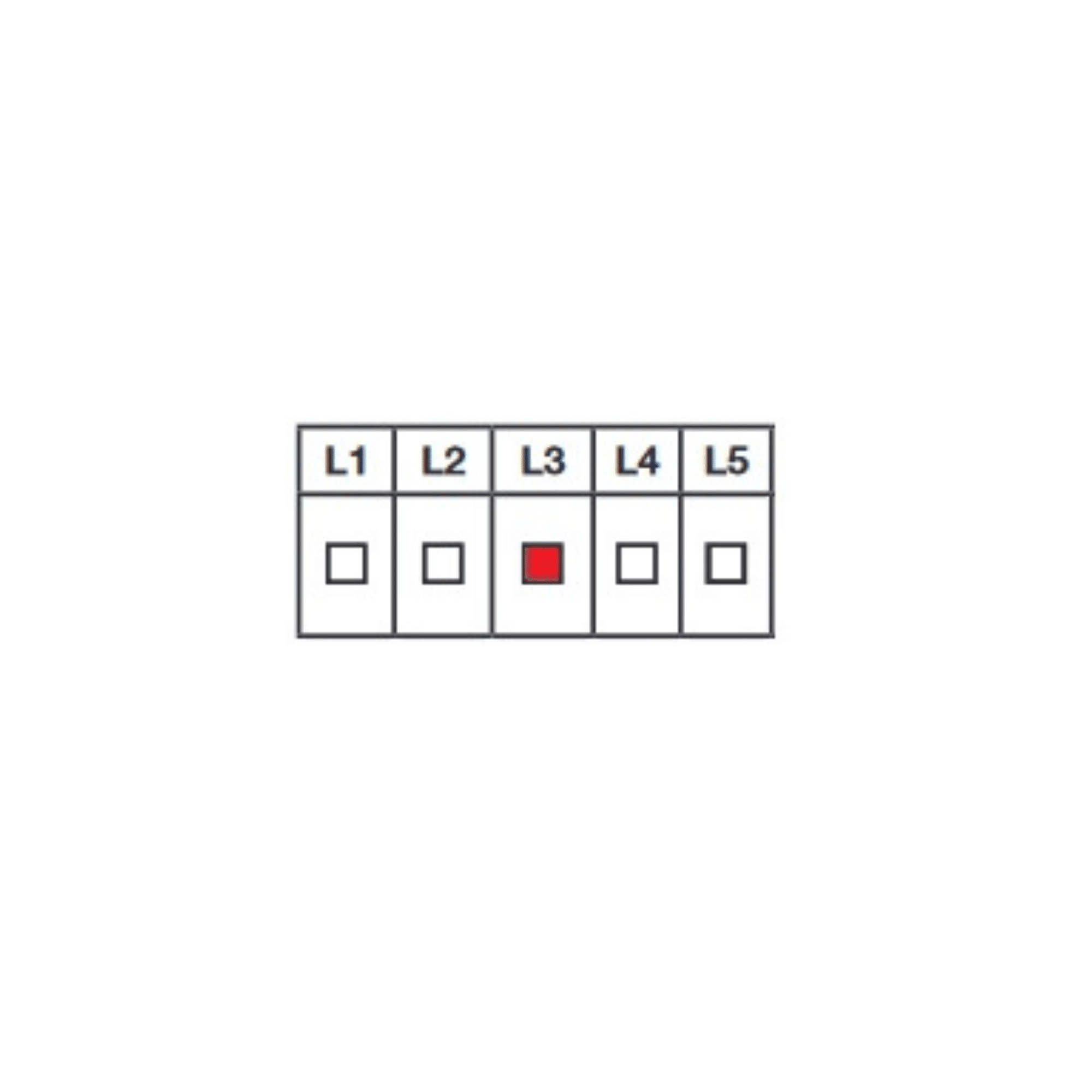
This error code indicates a short-circuit on the card’s +12V output.
NOTE: If you disconnect the photocells, remember to perform an electrical reboot of the board. |
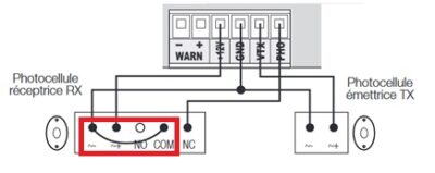
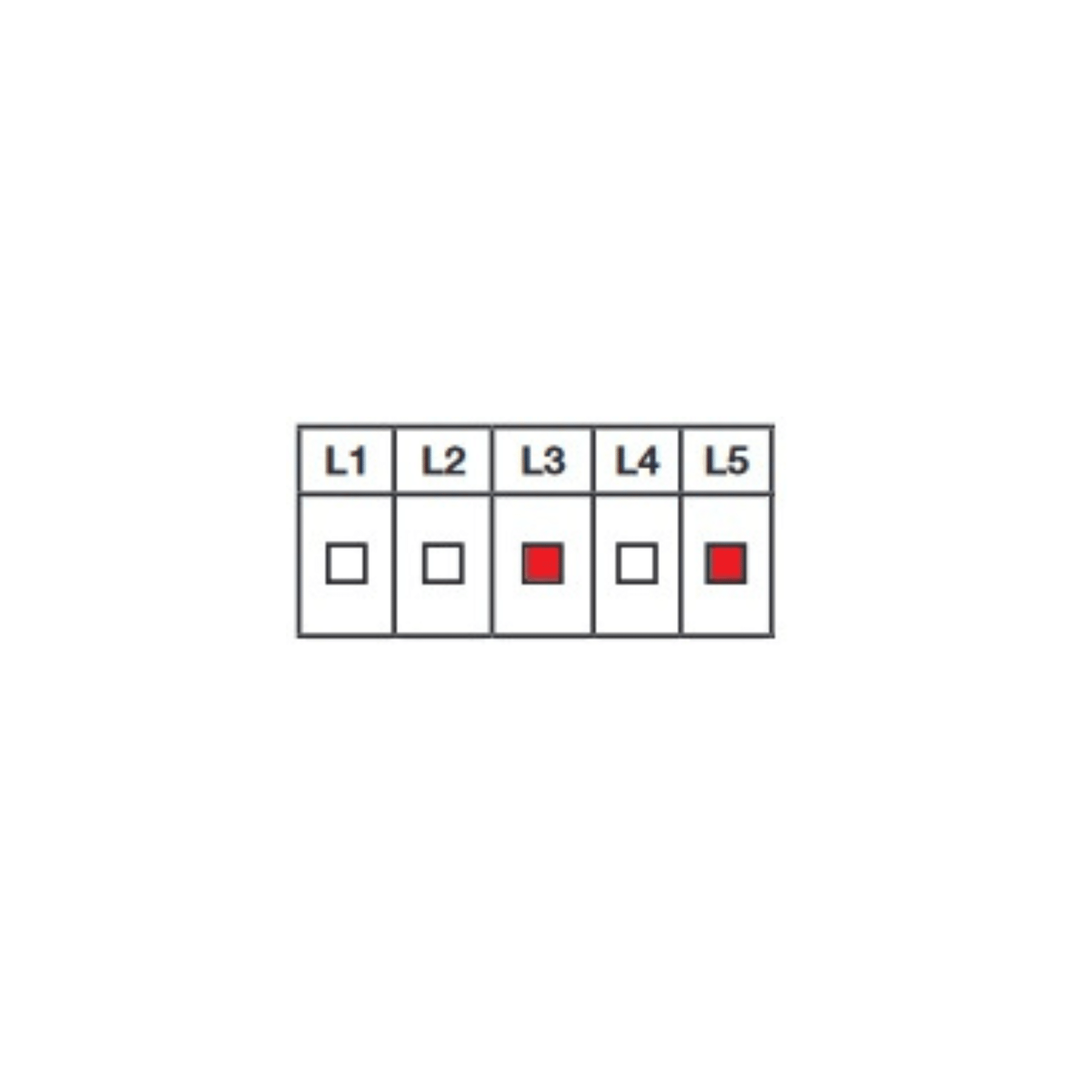
This error code is the result of a photocell self-test (see Appendix 5).
This error code is normal if you do not have photocells connected to the board.
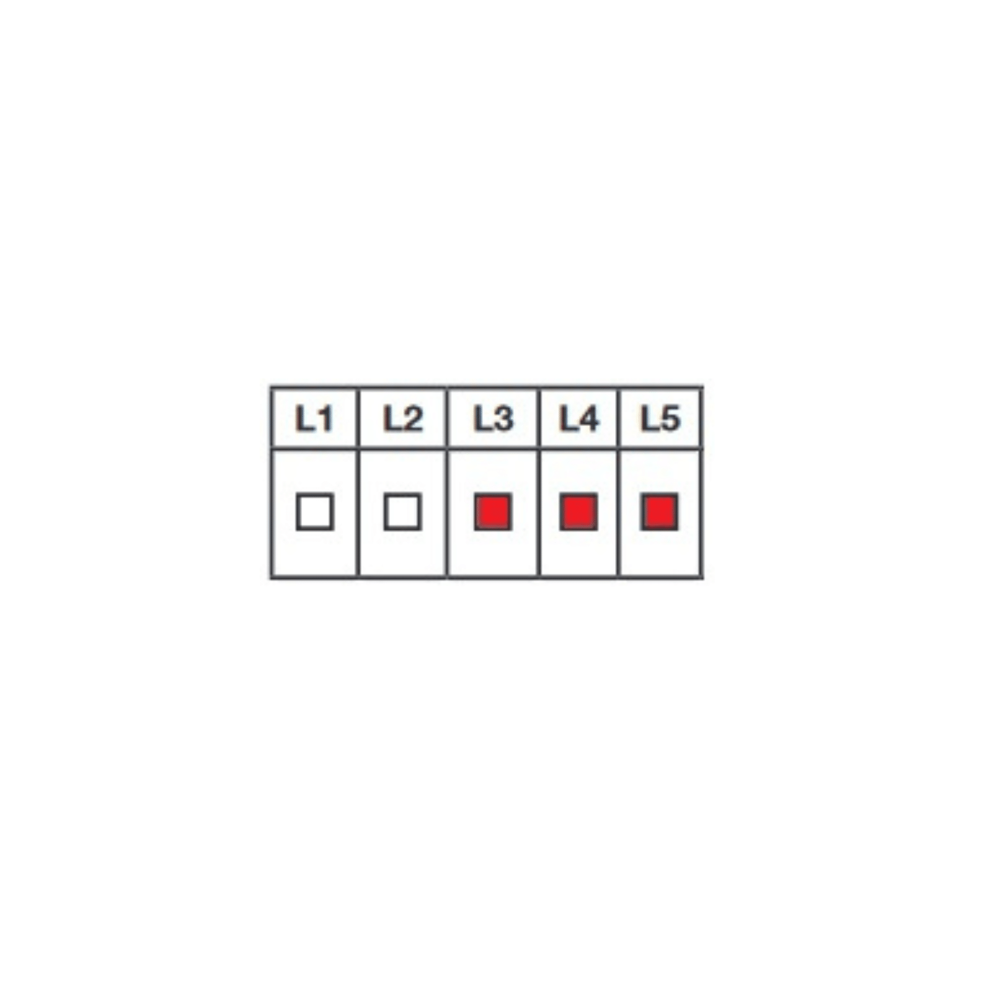
This error code indicates that the card has never seen the receiver photocell relay closed.
It is important to check when this error code appears.
|
|
|
|
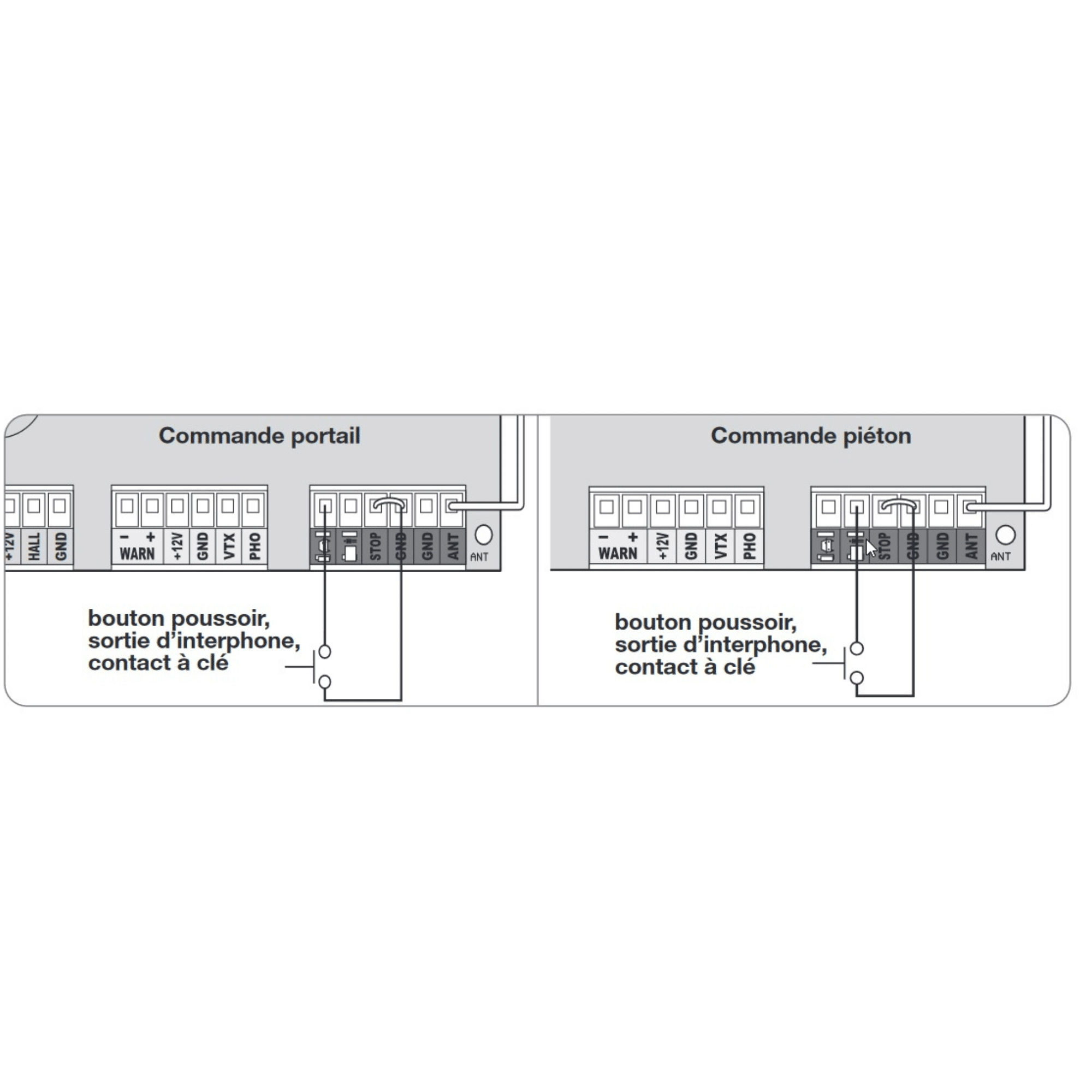
This error code indicates that a wired control device connected to the board has its contact permanently closed.
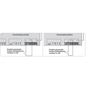
|
|
|