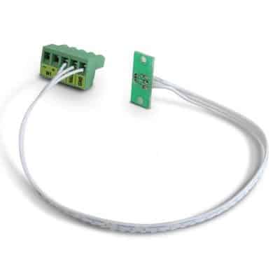
As mentioned in the introduction, this element tells the electronic board whether the motor is running or not. In the event of a Hall effect card fault, the electronic board will react as if the motor were not running, and will indicate corresponding errors.
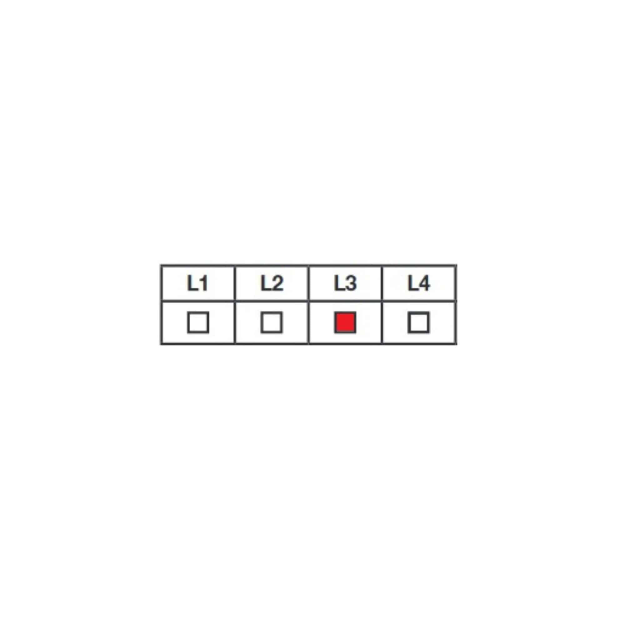
Typically, during self-learning, you’ll get the L3 error message after a short motor run (the motor has reached its opening stop in less than 3s).
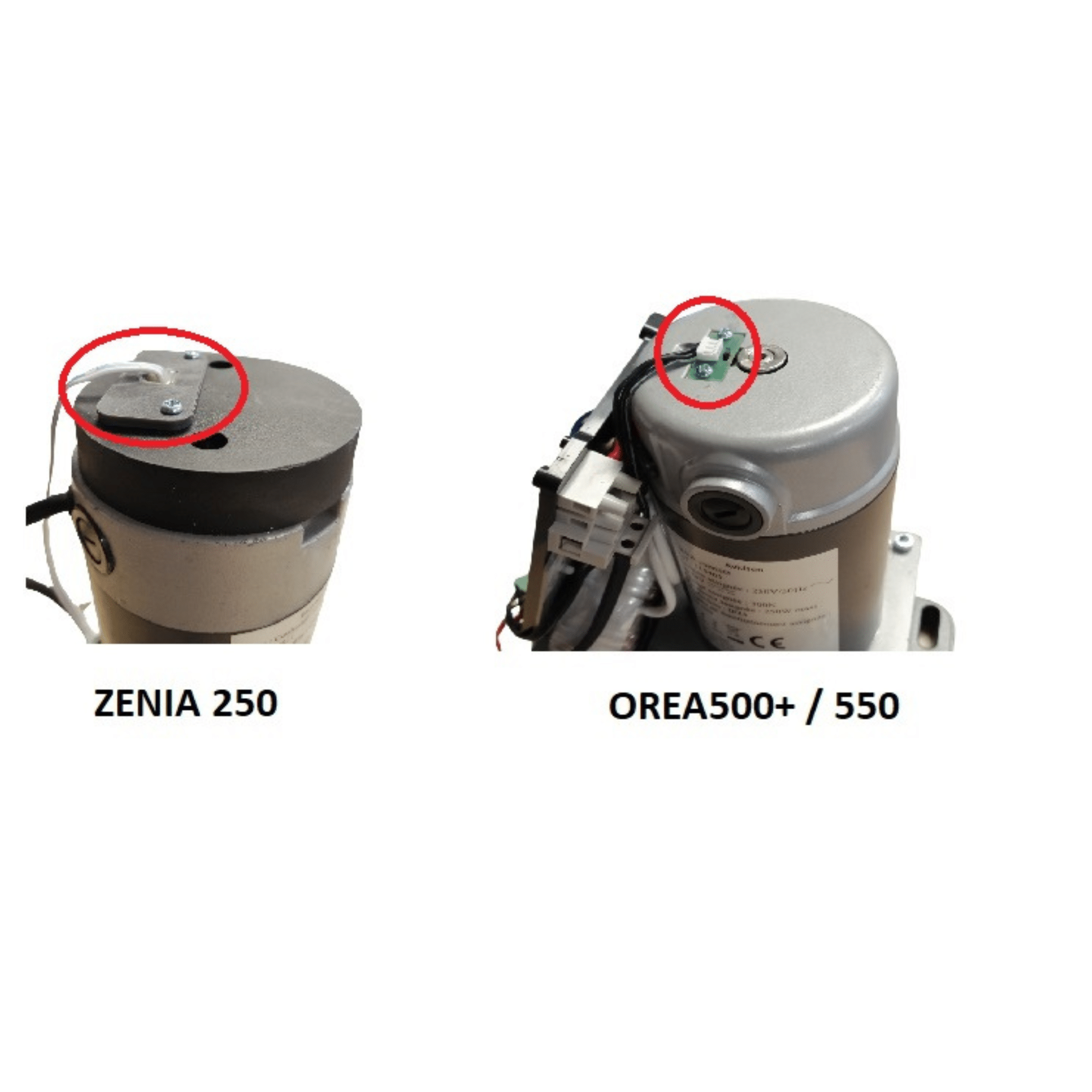
Before validating this fault, check that the magnet positioned next to it is firmly attached to the motor shaft and rotates with it.
Also check that all red LEDs on the board light up after a short press on the SET key.
Sometimes it can short-circuit, blocking the board’s electrical start-up.
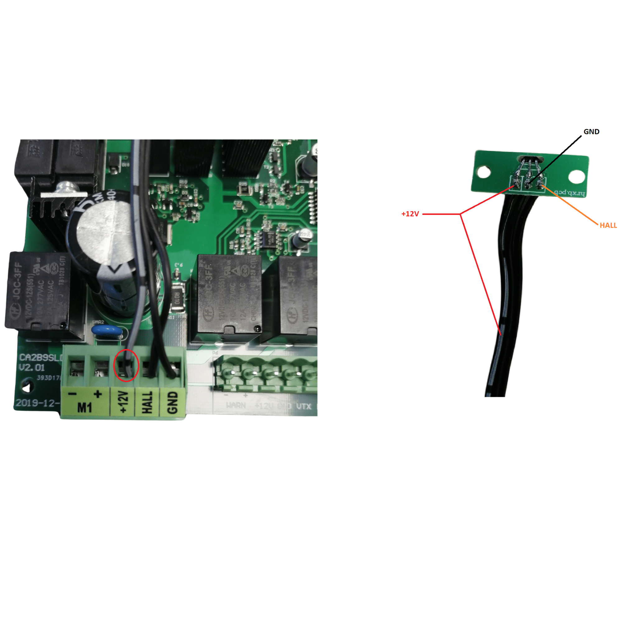
If you notice that your electronic board no longer has any warning lights, or that they are only dimly lit, disconnect the terminal block motor from the board, and check that it restarts properly.