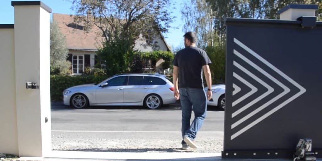
Let’s take the example of the Avidsen Orea 550 sliding gate motorization (reference 114460), but the principle remains the same for most sliding motors.
Full video editing
In this comprehensive video, we show you step-by-step how to install a sliding gate operator yourself.
All stages of sliding motor assembly
Step 1 - Kit contents.
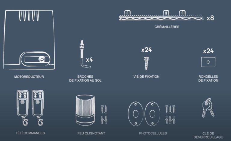
Example of the Avidsen Oréa 550 motor:
- Geared motor
- 8 racks (4m in all)
- Flashing light
- 2 remote controls
- 24 mounting washers
- 24 fixing screws
- 4 floor-mounting pins
- Unlocking key
- 1 pair of photocells
Step 2 - Installation hardware
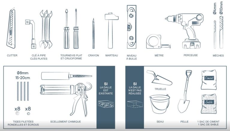
You will need a minimum of equipment to install the motorization. These include: a box cutter, a 10 mm pipe wrench, 2 13 mm open-end wrenches, a flathead and Phillips screwdriver, a pencil, a hammer, a spirit level, a tape measure, a drill and a 4 mm and a 10 mm drill bit.
For fixing to the slab: 4 threaded rods, diameter 8mm and length 15 to 20 cm + 8 washers and 8 nuts. 1 chemical sealant kit
Step 2 bis - wiring
The necessary wires need to be run:
- motor power supply: 3 wires of 1.5 mm² minimum
- photocell power supply: 6/10 cable
- power supply for flashing light: 6/10 cable
Step 3 - Installing the gate operator
Step 3.1: Fixing the motor to the floor
First, before you run out of space, you need to lay out the racks along the gate to determine the required length. Transfer the measurements to the racks. Start with the gate closed and move towards the opening. If necessary, cut off the last piece of rack so that it doesn’t end up in the vacuum.
Install the motor on a dry, hard surface. Do not install the engine block on earth or grass. Check slab level. Water must not be allowed to stagnate under the motor. If possible, leave a gap between the floor and the engine block.
To mark the location of the holes to be drilled in the concrete, position the installation template and mark out the holes. Be sure to maintain a distance of 5.5 cm between the template and the gate.
Drill and fasten threaded rods with chemical sealant.
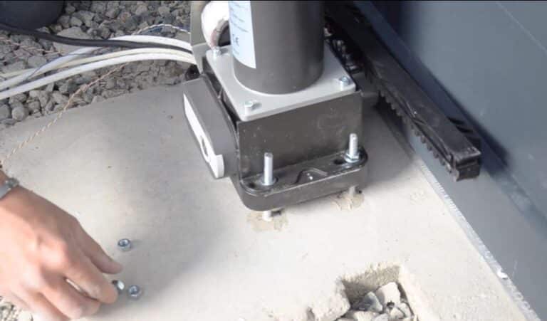
Once dry, pass the wires through the motor gap and position the motor block, ensuring that the screws are level.
Secure the motor block with washers and screws.
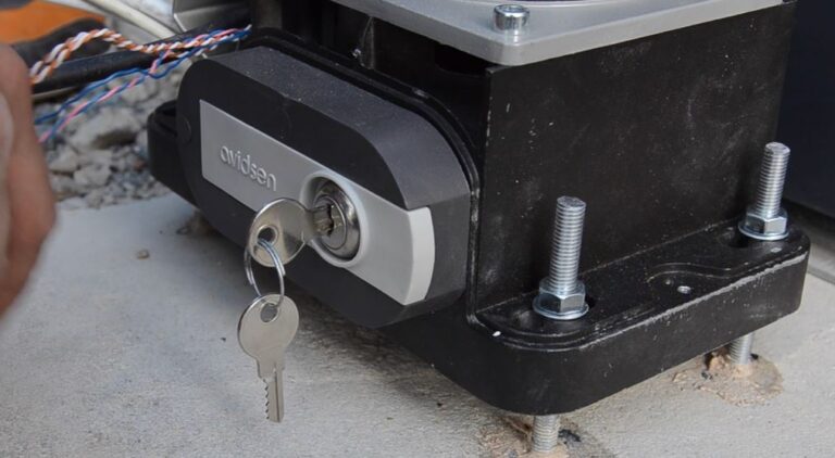
Disengage engine
Use the key supplied to disengage the motor and operate the gate manually.
Step 3.2: Attaching the racks to the gate
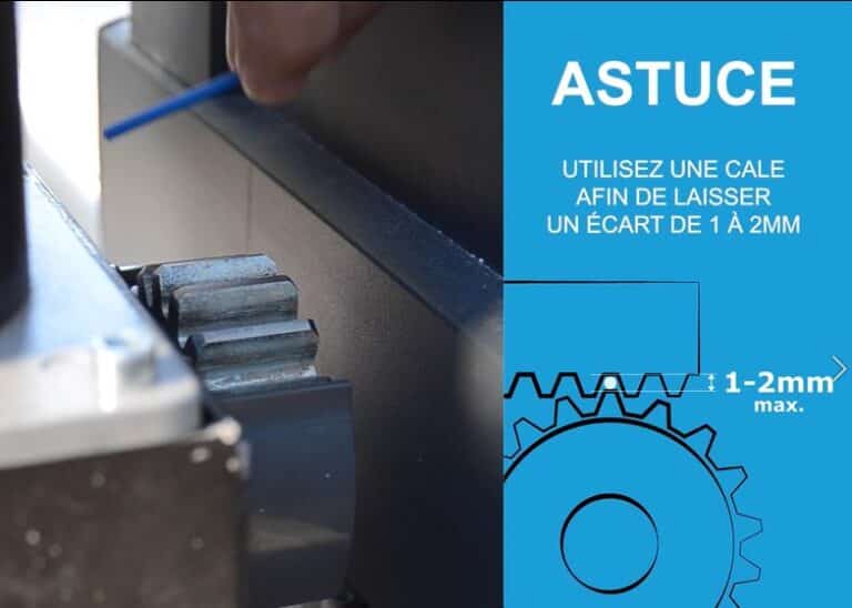
TIP: to leave enough space between the rack and the gearwheel, use a shim to leave a gap of 1 to 2 mm.
- Then attach the racks, resting on the gear wheel.
- Check level
- Then fasten the racks using the screws supplied.
- Then move on to the second section of rack and so on.
Step 3.3: Attaching the turn signal light
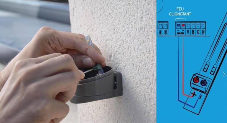
The flashing light must be mounted on the top or side of the pillar to which the control box is attached, and must be visible from both inside and outside.
- After drilling and dowelling the pillar, attach the flasher bracket.
- Position the flasher body and screw in place.
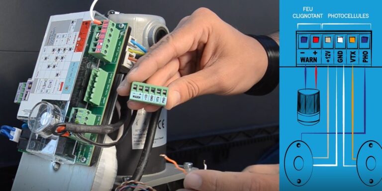
- Connect the wires as shown in the wiring diagram (WARN slot on the circuit board).
- Position the upper part of the blinker light and screw it in place.
Step 3.4: Photocell mounting
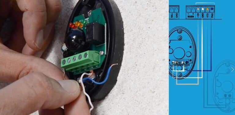
IMPORTANT: Photocells must be perfectly aligned and parallel. Receiver photocells (RX is marked on the back) must be mounted on the same side of the gate as the gate motor.
- Fix the base of the first receiver photocell (RX ) after drilling and dowelling the pillar.
- Connect the wires of the first photocell as shown in the wiring diagram.
- Fit the gasket supplied, then close the cover and do the same with the second photocell.
- Connect the wires of the second transmitter photocell (TX) as shown in the wiring diagram.
- Fit the gasket supplied, then close the cover.
Step 4 - Electrical connections
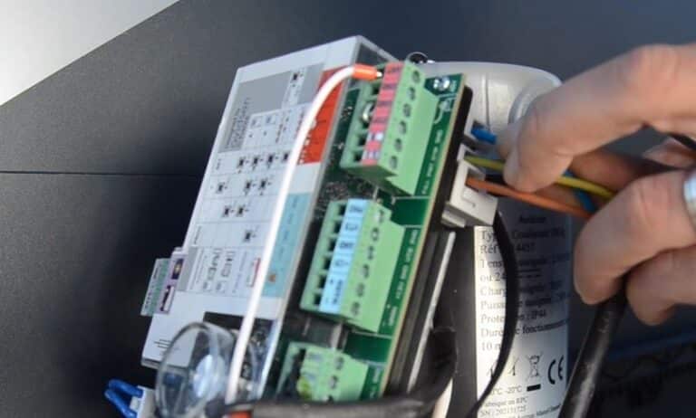
Step 4.1: Mains connection
- Make the connection on the motor side
IMPORTANT: The power line used must be exclusively reserved to supply the gate operator and protected by a fuse or circuit breaker (6A min., 16A max.) and a differential device (30mA).
- Make the connections at the electrical panel, ensuring that it is in the OFF position.
Step 4.2: Photocell and flashing light connection
Connect the photocells and flashing light as shown in the wiring diagram:
Photocell :
- +12V: + from RX photocell
- GND: + from photocell TX and RX
- VTX: + of TX photocell
- PHO: NC of RX photocell
- Do not forget the shunt between – and COM on the RX photocell.
Flashing light :
- +
- –
Step 5 - Basic settings
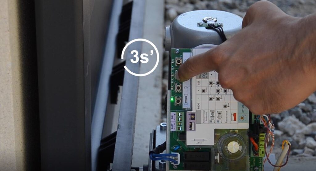
Step 5.1: Self-learning
ATTENTION: If your gate opens instead of closing, this means that the motor is connected the wrong way round.
- Press PLUS for 3 seconds: gate closes
- Then the gate opens
- the gate closes again
Step 5.1 .1: If gate opens instead of closing
- Press SET to stop teach-in
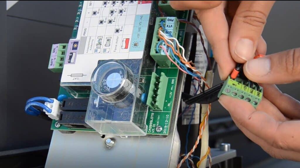
- Change motor polarity: the direction in which the motor is connected depends on the direction in which the gate opens.
Then restart Self-Learning: Step 5.1
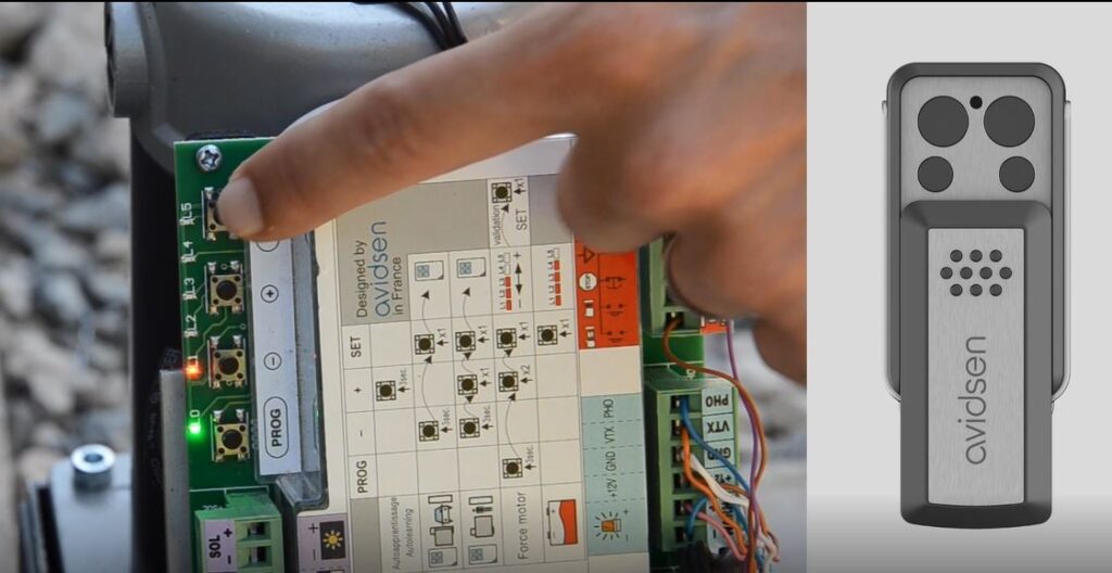
Step 5.2: Remote control for total opening programming
- Press the MINUS button until the red L1 LED lights up.
- Press the SET button.
- Then press the button on the remote control on which you want the door to open completely.
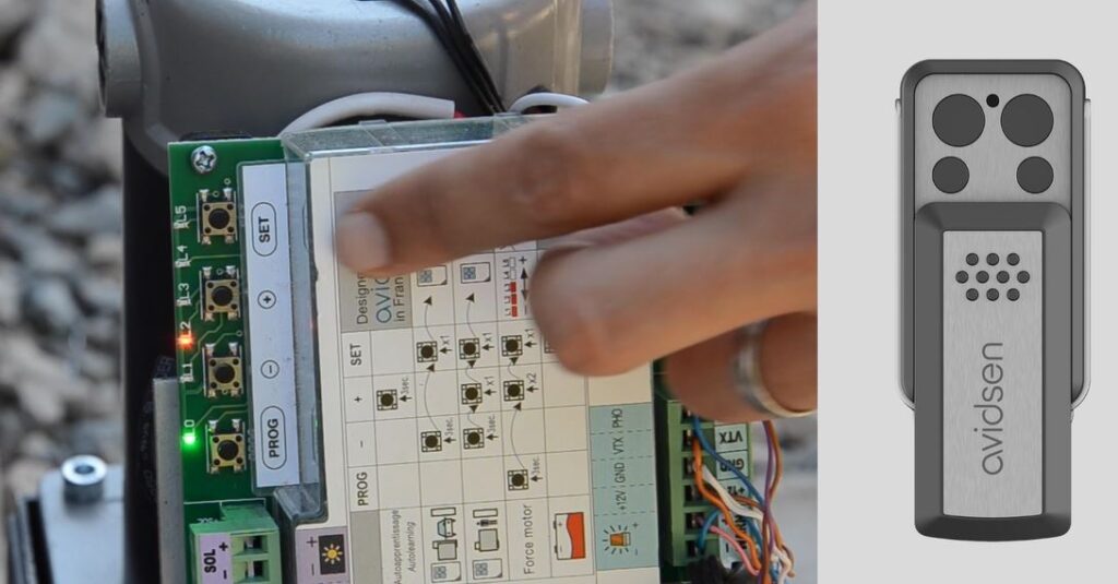
Step 5.3: Remote control of partial opening programming
- Press the MINUS button until the red L1 LED lights up.
- Press the PLUS button
- Press the SET button.
- Then press the button on the remote control on which you want partial opening (pedestrian).
Step 6 - Advanced settings
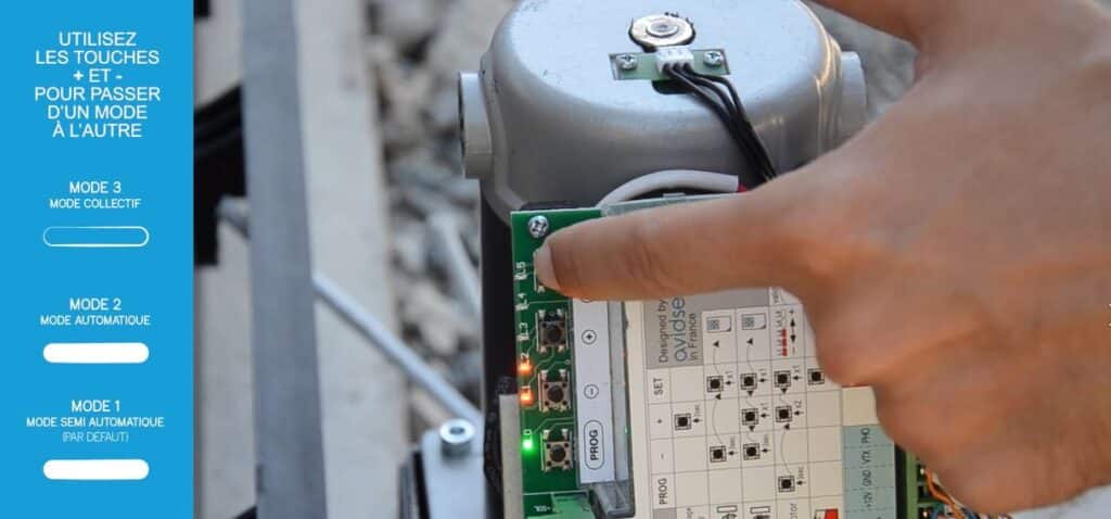
Step 6.1: Automatic closing: 3 operating modes
- Press PROG for 3s, L1 lights up
- Press PLUS 3 times, L4 lights up
- Press SET to enter the auto close menu
- 3 modes
- L1 on = Semi-automatic mode: one command to open and one command to close
- L2 on = Automatic mode: gate closes after x seconds. This value depends on the time delay setting (default 30s).
- L3 on = collective mode: automatic mode with some differences. It is not possible to stop the gate during opening. A command given during the timer does not stop it, but restarts it. If a command is received during closing, the gate reopens instead of stopping. Pedestrian mode is not active.
To change modes, press + or – to light up the number of LEDs corresponding to the required mode.
REMINDER: photocells are mandatory for automatic closing and collective mode.
- Press SET to confirm the selected mode
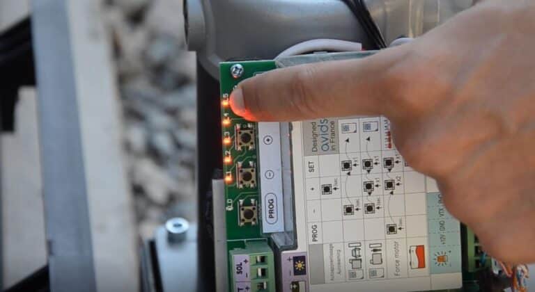
Step 6.2: Motor force adjustment
- Press PROG for 3s, L1 lights up
- Press PLUS 2 times, L3 lights up
- Press SET to enter the motor force menu
- L0 on only = level 1 = low force
- L1 on = level 2
- L2 on = level 3
- L3 on = level 4
- L4 on = level 5
- L5 on = level 6 = strongest force
- Press SET to confirm the selected mode
REMINDER: Self-learning is mandatory after changing this setting.
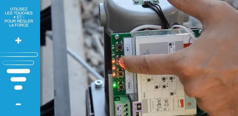
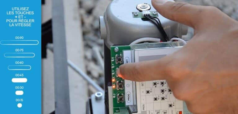
Step 6.3: Setting the waiting time before automatic closing
- Press PROG for 3s, L1 lights up
- Press PLUS 4 times, L5 lights up
- Press SET to enter the timer menu
-
- L0 on only = 15 seconds
- L1 on = 30 seconds
- L2 on = 45 seconds
- L3 on = 1 minute
- L4 on = 1 minute and 15 seconds
- L5 on = 1 minute and 30 seconds
- Press SET to confirm the desired time delay
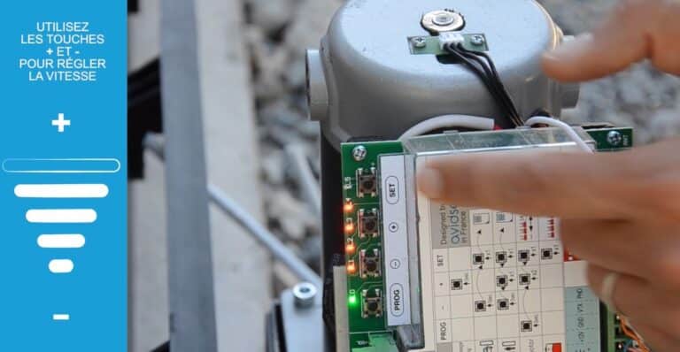
Step 6.4: Setting the gate speed
- Press PROG for 3s, L1 lights up
- Press PROG 2ᵉ times for 3s
- Press SET to enter the speed menu
-
- L0 on only = level 1 = slowest
- L1 on = level 2
- L2 on = level 3
- L3 on = level 4
- L4 on = level 5
- L5 on = level 6 = fastest
- Press SET to confirm the desired speed
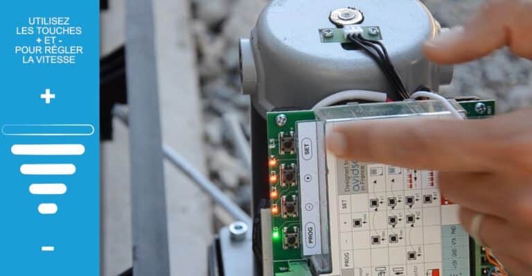
Step 6.5: Setting gate acceleration and idle speed
- Press PROG for 3s, L1 lights up
- Press PROG 2ᵉ times for 3s
- Press PLUS once, L2 lights up
- Press SET to enter the gate acceleration and deceleration menu
-
- L0 on = level 1 = longest acceleration
- L1 on = level 2
- L2 on = level 3
- L3 on = level 4
- L4 on = level 5
- L5 on = level 6 = shortest acceleration
- Press SET to confirm the selected mode
Step 6.6: Removing remote controls
- Press MINUS 3s, until L1 LED lights up
- Press PLUS, L2 lights up
- Press PLUS, L3 lights up
- Press SET, all LEDs light up
- Press SET until LEDs flash
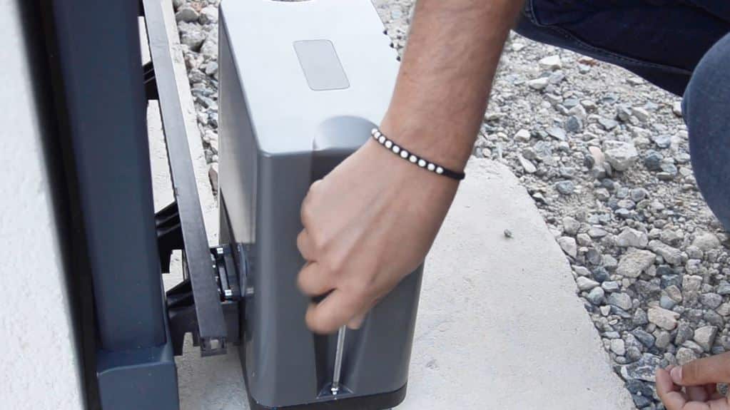
Step 6.7: Reinstalling the engine cowling
Replace the engine cover.
Step 7 - Advanced settings
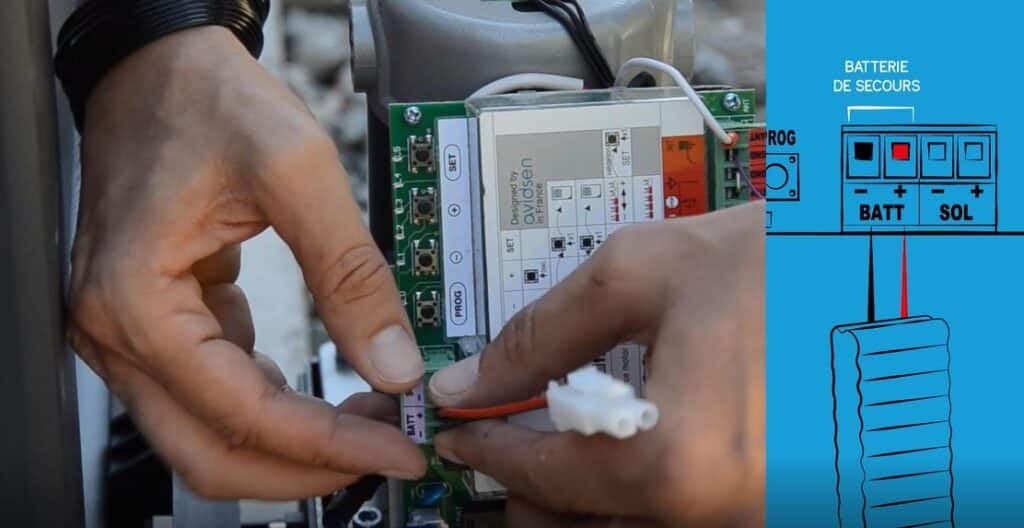
Step 7.1: Installing the 12 V emergency battery
- Red wire on BAT+ (plus)
- Red thread on BAT – (minus)
Step 7.2: Adding an additional remote control, total opening
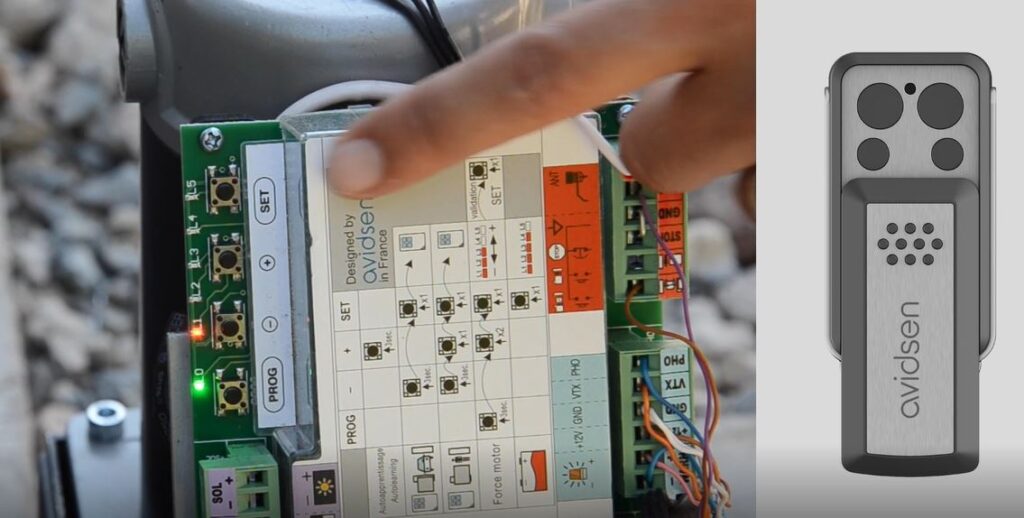
- Press the MINUS button until the red L1 LED lights up.
- Press the SET button.
- Then press the button on the remote control on which you want the door to open completely.
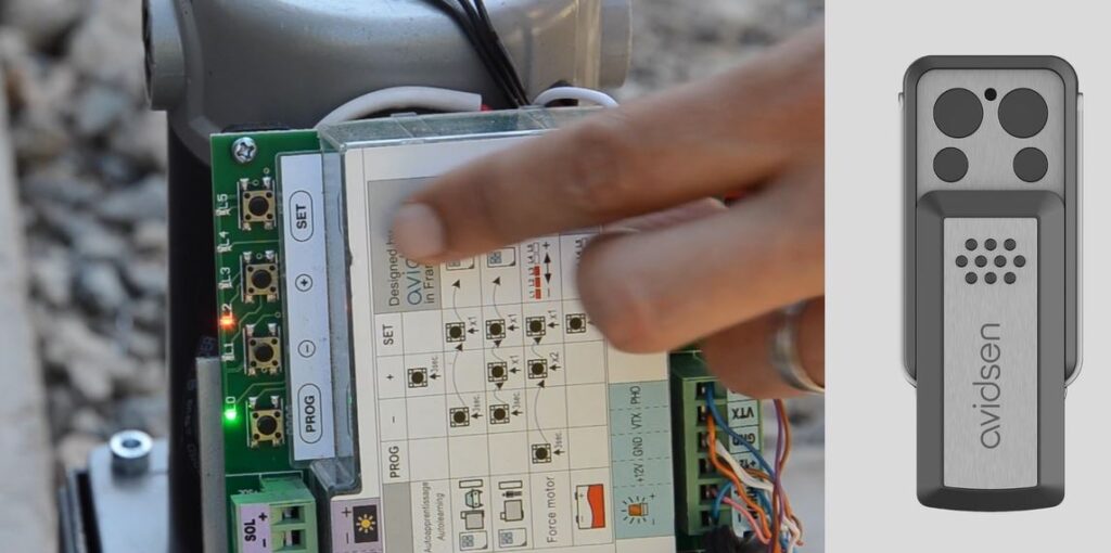
Step 7.3: Adding an additional remote control, partial opening
- Press the MINUS button until the red L1 LED lights up.
- Press the PLUS button
- Press the SET button.
- Then press the button on the remote control on which you want partial opening (pedestrian).
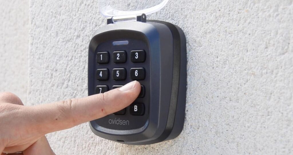
Step 7.4: Programming the keypad
Access code modification
- Enter master code : B99999
- Enter settings: key 2 then B
- Enter new code: XXXX then press B
- LED flashes
- Enter your new code 2ᵉ times: XXXX then press key B
Step 8 - Commissioning
Check all functions:
- total opening
- partial opening,
- automatic closing
- obstacle detection
- battery backup
